
The Extended Double Zeppelin 'Zepp' (EDZ) is a copper wire antenna and is probably the most successful wire antenna ever developed. The antenna was used on Zeppelins in the 1920's and 1930's, hence the name.
11 m Band "Zepp" (EDZ) antenna centred at 27.500 MHz
The EDZ is a non-resonant antenna which provides approximately 9 dB gain over a dipole mounted at the same height due to its longer length. At 1.28 wavelength (Lambda) the EDZ is the longest "dipole" antenna. The ideal minimum height for the EDZ above ground is 0.6 Lambda. At this height an acceptable balance between losses and radiation pattern/gain is achieved.
The take-off/elevation angle of approximately 22 degrees makes the EDZ a great DX antenna for transmission and reception respectively. This antenna is great for reception on other HF frequencies too and is ideal for short-wave listeners (SWL's).
The EDZ is a bi-directional antenna and its radiation pattern (indicated in figure 1) consists of two main lobes carrying most of the power and four smaller lobes, one on each side of the main lobes. The horizontal beam width at the -3 dB points is approximately 41 degrees and the vertical beam width at the -3 dB points is approximately 24 degrees so it is important to "point" the broadside of the antenna in the direction of interest (refer to figure 4).
Although maximum gain for transmission and reception takes place in the two main lobes, a small amount of power is lost in the smaller side lobes during transmission and similarly signals/noise, although attenuated, are received via the smaller side lobes during reception.
"VOACAP HF Propagation Prediction and Ionospheric Communications Analysis" is a very useful online tool to determine bearings of areas of interest: http://www.voacap.com/, specifically the "Point-to-Point Predictions."
My station is located in South Africa and my areas of interest lie towards the East/West Coast of the USA and Australia (via short-path) and Hawaii/Pacific Islands (via long-path). The antenna is thus pointed broadside at a bearing of 130 degrees and 310 degrees; the ends of the antenna pointing to 40 degrees and 220 degrees.
It is important to note that True North and Magnetic North are not the same and differ significantly in different parts of the world. Look up the difference for your area and compensate for the difference when "pointing" your antenna using a compass.
Visit "Wikihow" for different methods to find True North: http://www.wikihow.com/Find-True-North-Without-a-Compass.
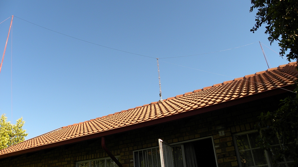
The EDZ is easy to construct and is relatively stealthy as it is constructed with thin insulated copper wire. The most visible part of the antenna is the 450 ohm ladder line (refer to figure 2).
For this design I used standard PVC insulated electrical copper wire. With respect to RF, the PVC insulation causes the wire to appear longer than it really is, this is caused by a phenomenon called "velocity factor." This has been taken into account and the dimensions I use here have been decreased by 6 % (factor: 0.94) which is the velocity factor of standard PVC insulated electrical copper wire.
Full wavelength: 300 / 27.555 = 10.887 x 0.94 = 10.234 m
Top sections of antenna: 0.64 wavelength: 10.234 x 0.64 = 6.550 m (for each leg)
450 ohm Ladder Line: 0.2 wavelength: 10.234 x 0.2 = 2.047 m (the length may vary between 1.300 m and 2.047 m depending on surroundings and ground type, use trial-and-error to find the ideal feed-point for your antenna; you may consider starting at 2.047 meters and shortening as required. In my case the ideal length is 1.370 m).
The EDZ is a balanced antenna and has a high impedance at the feed point. To connect the antenna to 50 ohm coax, which is also un-balanced, it is necessary to transform the high impedance to 50 ohm and to convert the balance to an un-balance respectively. A 450 ohm Ladder Line 0.2 Lambda in length transforms the high impedance of the antenna to 50 ohm and the Current Balun converts the balance to an un-balance; hence the name "bal" for balanced and "un" for un-balanced.
The measured band width of this EDZ is 1 MHz at the 1:1.5 VSWR points. I measured the VSWR of the EDZ and found it to be less than 1:1.1 at 27.500 MHz and 1:1.5 at 27.000 MHz and 28.000 MHz respectively (refer to figure 3). To adjust/tune the VSWR remove or add wire to the 450 ohm Ladder Line.
Running this design in EZNEC produces VSWR and Radiation Pattern plots as indicated in figures 5, 6 and 7 respectively. I selected sandy, dry ground (the antenna is mounted over a house built with concrete and bricks) and PVC insulated copper wire 0.6 mm thick in the simulation. The antenna was placed 7 m above the ground. The results indicate that the theoretical VSWR and the VSWR I measured are very similar and the take-off angle is 22 degrees. Figure 8 shows the EZNEC antenna model and current distribution curves.
Before tuning, ensure the coax cable transmission line is cut to a length which uses multiples of 0.5 wavelength because each 0.5 wavelength of cable represents the characteristic impedance of 50 ohm. Also take the velocity factor (VF) of the cable into account. The VF for RG58/U Solid Polyethylene (inside insulation: transparent) is 0.66 and for Foam Polyethylene (inside insulation: white) is 0.78 respectively. Solid Polyethylene coax cable one 0.5 wavelength long is 3.600 metres. The calculation (in metres) is as follows: 300/27.500X0.66/2 = 3.600 m. This length does not include the extra coax cable required for the Balun, it is only the length of the coax cable transmission line from the Balun to the receiver or transceiver.
It is important to keep the 450 ohm Ladder Line and 50 ohm coax perpendicular to the antenna for the longest distance possible, in doing so there is less chance for RF being conducted back into the feed line and ultimately into the transmitter. The 450 ohm Ladder Line should also not be twisted so that the two wires touch and not be bent at sharp angles (avoiding angles less than 90 degrees). The EDZ itself should be pulled as straight as possible. Bends in the wire distort the radiation pattern of the antenna which affects gain and directivity respectively. As with most antennas, try to install the antenna as far away as possible from surfaces and objects that reflect RF.
If you have the space why not try building an EDZ, it's a classic antenna and it works well ... enjoy.
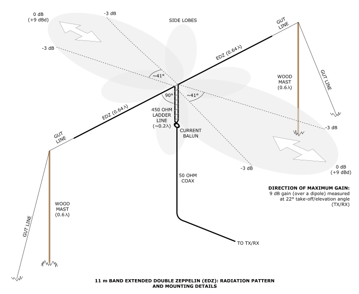
Figure 1: 11 m Band "Zepp" (EDZ) antenna: Radiation pattern and mounting details
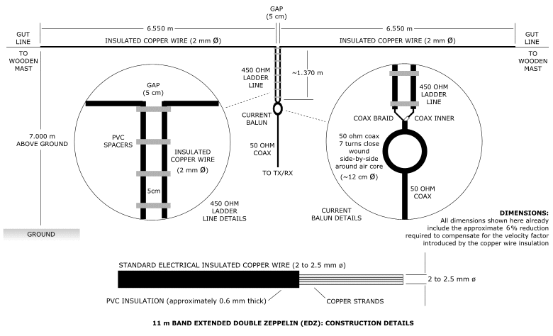
Figure 2: 11 m Band "Zepp" (EDZ) antenna: Construction details
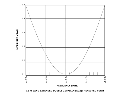
Figure 3: 11 m Band "Zepp" (EDZ) antenna: Measured VSWR
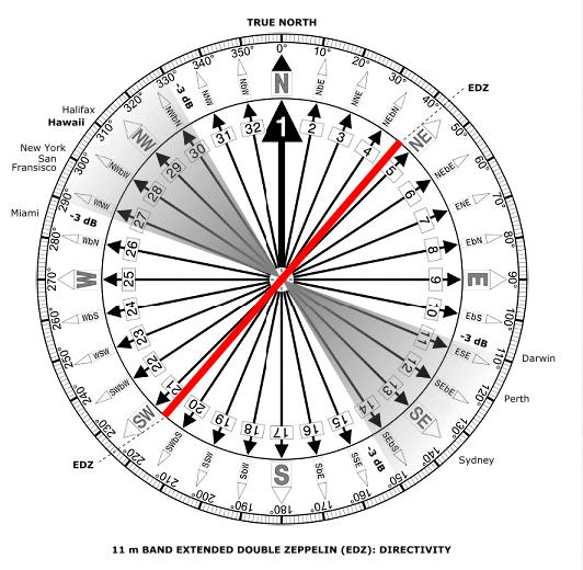
Figure 4: 11 m Band "Zepp" (EDZ): antenna Directivity
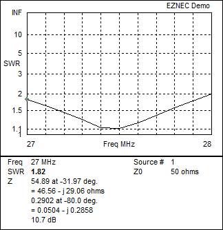
Figure 5: 11 m Band "Zepp" (EDZ): EZNEC VSWR
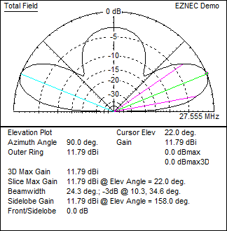
Figure 6: 11 m Band "Zepp" (EDZ): EZNEC side view radiation pattern
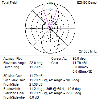
Figure 7: 11 m Band "Zepp" (EDZ): EZNEC top view radiation pattern
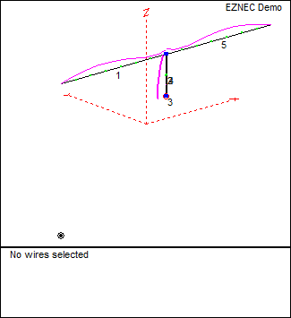
Figure 8: 11 m Band "Zepp" (EDZ): EZNEC antenna model
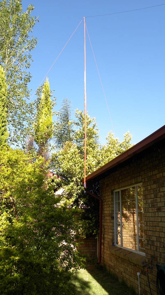
11 m Band "Zepp" (EDZ) antenna: Wooden mast
(click on the image for a larger version)
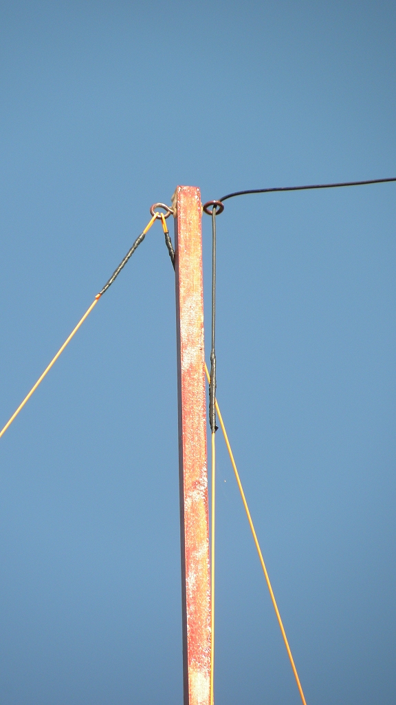
11 m Band "Zepp" (EDZ) antenna: Rings
(click on the image for a larger version)
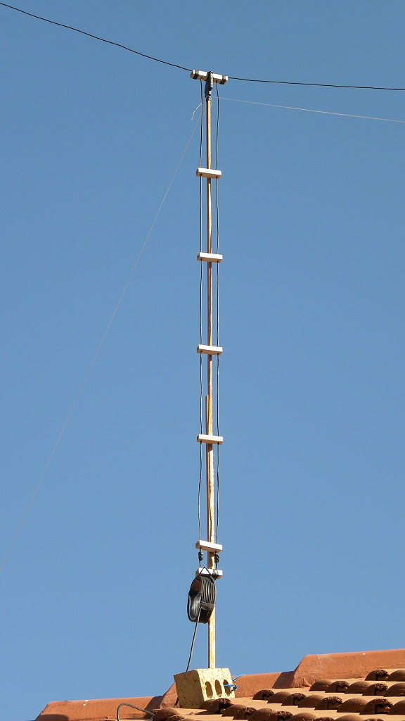
11 m Band "Zepp" (EDZ) antenna: 450 ohm Ladder Line
(click on the image for a larger version)
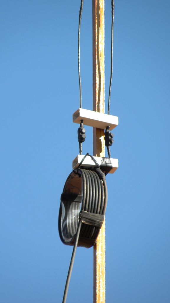
11 m Band "Zepp" (EDZ) antenna: Current Balun
(click on the image for a larger version)
| Type | 1.28 Lambda Extended Double Zeppelin (EDZ) PVC insulated copper wire antenna |
| Frequency | 11 meter Band (centred at 27.500 MHz) |
| Directivity | Bi-directional |
| Gain | Approximately 9 dBd (9 dB gain over a dipole at the same height) |
| Beam width |
Horizontal: Approximately 41 degrees broadside to antenna (measured at the -3 dB points) Vertical: Approximately 24 degrees (measured at the -3 dB points) |
| Band width | 1 MHz (measured at the 1:1.5 VSWR points) |
| Take-off/elevation angle | Approximately 22 degrees |
| Height above ground | 7.000 m (0.6 Lambda) minimum |
| Antenna length | 13.100 m (1.28 Lambda) with each leg 6.550 m (0.64 Lambda) |
| 450 ohm ladder line length | Approximately 2.047 m (0.2 Lambda) with 5 cm spacing between the two wires |
| Antenna wire | 2 to 2.5 mm diameter standard PVC insulated electrical copper wire with insulation approximately 0.6 mm thick |
| Current Balun | 7 turns of RG-58U coax close wound side-by-side with a 12 cm diameter air core |
| VSWR | Less than 1:1.1 at 27.500 MHz and 1:1.5 at 27.000 MHz and 28.000 MHz respectively |
Antenna's
 Contents and images
© 1998 to 2024 RaptorZone v8.0
All rights reserved