
Had enough of strong winds destroying your antennas and/or looking for a very stealthy small antenna that produces a horizontally polarized omni-directional radiation pattern in a confined electric field for maximum radiation efficiency? The Cobwebb antenna may be the answer! My design is based on the well-known Cobwebb antenna using standard speaker cable, however only one Gamma matched dipole will be constructed for 11 m Band use.
11 m Band Cobwebb antenna centred at 27.500 MHz
(click on the image for a larger version)
It's not a beam or high gain antenna, but according to online reviews it outperforms a vertical antenna at the same height. Being mounted horizontally it is a very "quiet" antenna making low S-unit copies easier and it causes very little to no RFI with the neighbors. My tests indicate that this is indeed true, noise is between 4 and 5 S-units less compared to a vertical at the same height and it has a receive gain of approximately 1 to 2 S-units over a vertical antenna at the same height.
The parallel anti-phase “sides” of the antenna cancel the radiation that would normally be wasted as high angle radiation from a straight dipole and fill in what would otherwise be the nulls off straight dipole ends. The resulting omni-directional pattern has many advantages over antennas with directional radiation patterns.
The electric field of the CobWebb is confined as a result of the high impedance ends of each element which are only a few centimeters apart, thus reducing coupling to nearby objects. The advantage here being that the antenna does not need re-tuning for operation at different heights and locations. Also, the radiated power is not absorbed by nearby objects, it is all radiated into free space. Breakthrough and noise pick-up are also at an absolute minimum and the ground conductivity and height do not affect antenna tuning.
The Cobwebb is relatively easy to construct using wood for the frame and standard speaker cable for the antenna. As the antenna is mounted outdoors it is exposed to the elements thus it is important to seal the wood. I used NOVA 14 polyurethane wood sealer paint which contains a water repellent, anti-fungal agent and is UV resistant. To make the connections waterproof tightly wrap them with self-amalgamating tape.
Pull the speaker cable around the wood frame ensuring it is as straight and as taught as possible. Excessive bends in the wire and/or sagging might distort the radiation pattern of the antenna which may affect the gain and overall performance. Fold the two open ends of the cable back on each other to form two loops (keep them in place by wrapping self-amalgamating tape around each end); tie the two open ends together with Dacron line.
To adjust the VSWR shorten or length both open ends of the cable by the same amount, pulling them together again with the Dacron line. Use trial-and-error to obtain the lowest VSWR.
Before connecting the antenna to the RG-58U coax cable transmission line, which is un-balanced, it is necessary to "convert" the balanced characteristics of the antenna to that of the un-balanced transmission line using a Current Balun. The Balun converts the balance to an un-balance; hence the name "bal" for balanced and "un" for un-balanced.
Before tuning the antenna, ensure the coax cable transmission line is cut to a length which uses multiples of 0.5 wavelength because each 0.5 wavelength of cable represents the characteristic impedance of 50 ohm. Also take the velocity factor (VF) of the cable into account. The VF for RG-58U Solid Polyethylene (inside insulation: transparent) is 0.66 and for Foam Polyethylene (inside insulation: white) is 0.78 respectively. Solid Polyethylene coax cable one 0.5 wavelength long is 3.600 metres. The calculation (in metres) is as follows: 300 / 27.500 x 0.66 / 2 = 3.600 m. This length does not include the extra coax cable required for the Balun, it is only the length of the coax cable transmission line from the Balun to the receiver or transceiver. Whether or not this is beneficial is a controversial subject, some say it is better to follow this procedure whereas others suggest it is not.
Gamma match dipole speaker cable measurements:
Total length: 5.250 m (cut cable a few cm longer than required to allow for length adjustment)
Two shorts: Each 1.586 m from the centre
Air gap between open ends: Approximately 10 cm (to be determined by trial-and-error)
Corner slots to mount speaker cable: 0.922 m (from the centre out on each of the four spreaders)
Running this design in EZNEC produces VSWR and Radiation Pattern plots as indicated in figures 3, 4 and 5 respectively. I selected average ground and copper in the simulation. The antenna was placed 11 meters above the ground. Figure 6 shows the EZNEC antenna model and current distribution curves. The EZNEC "wire" table is shown in figure 2.
If you have had enough of strong winds destroying your antennas and/or looking for a very stealthy small antenna try this one, it's a classic and it works very well. As with most antennas, try to install the antenna as far away as possible from surfaces and objects that reflect RF.
Important: Do not install the antenna near power lines or where it will cause damage to property or hurt people and pets should it fall over for any reason. To prevent lightning damage, disconnect the antenna from your receiver/transceiver when not in use.
Figure 1: 11 m Band Cobwebb antenna: Construction diagram
Figure 2: 11 m Band Cobwebb antenna: EZNEC Dimensions (11 m above ground)
Figure 3: 11 m Band Cobwebb antenna: EZNEC VSWR
Figure 4: 11 m Band Cobwebb antenna: EZNEC Vertical Radiation Pattern
Figure 5: 11 m Band Cobwebb antenna: EZNEC Horizontal Radiation Pattern
Figure 6: 11 m Band Cobwebb antenna: EZNEC Antenna Model
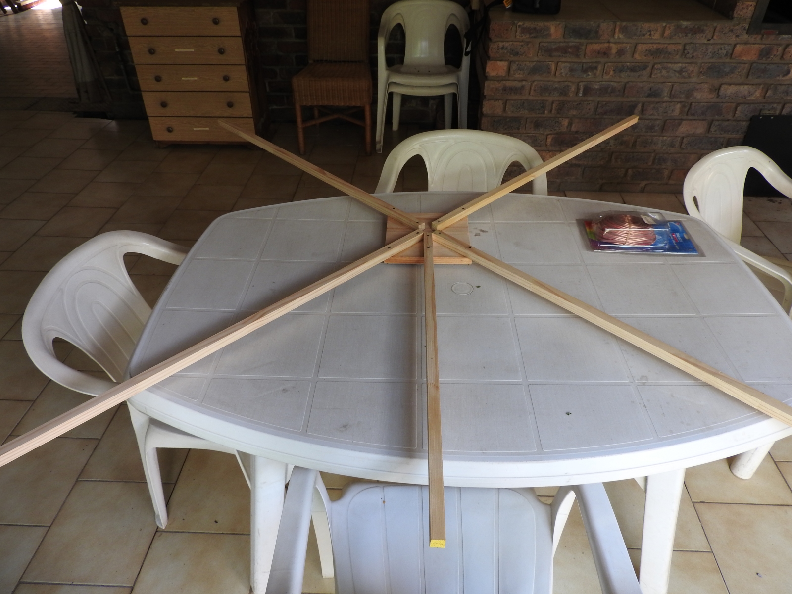
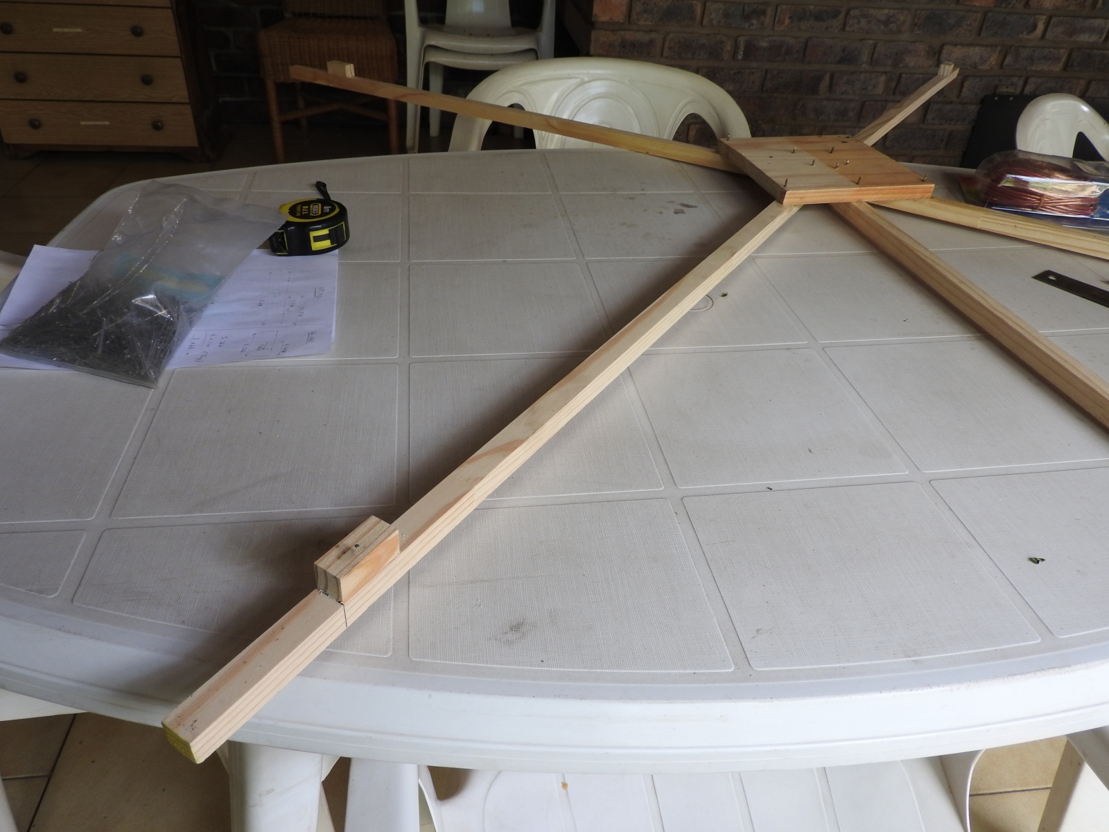
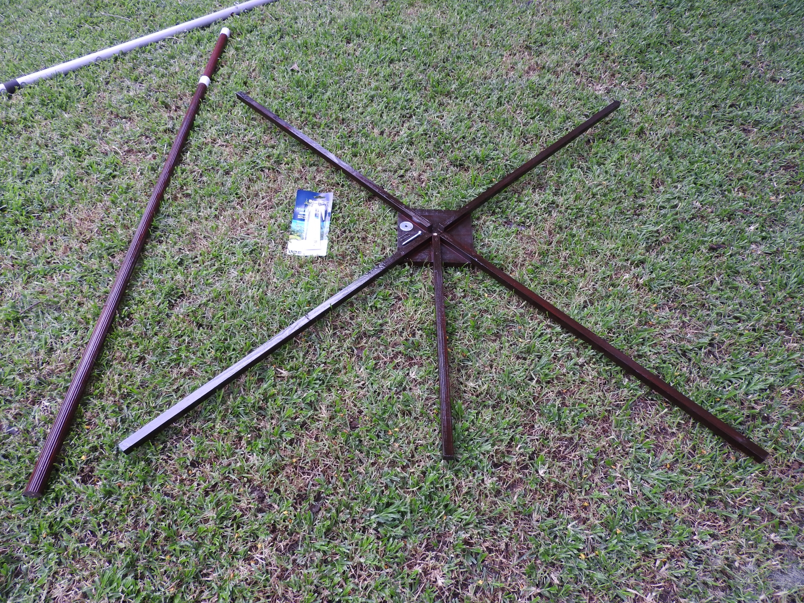
11 m Band Cobwebb antenna: Wood frame
(click on the image for a larger version)
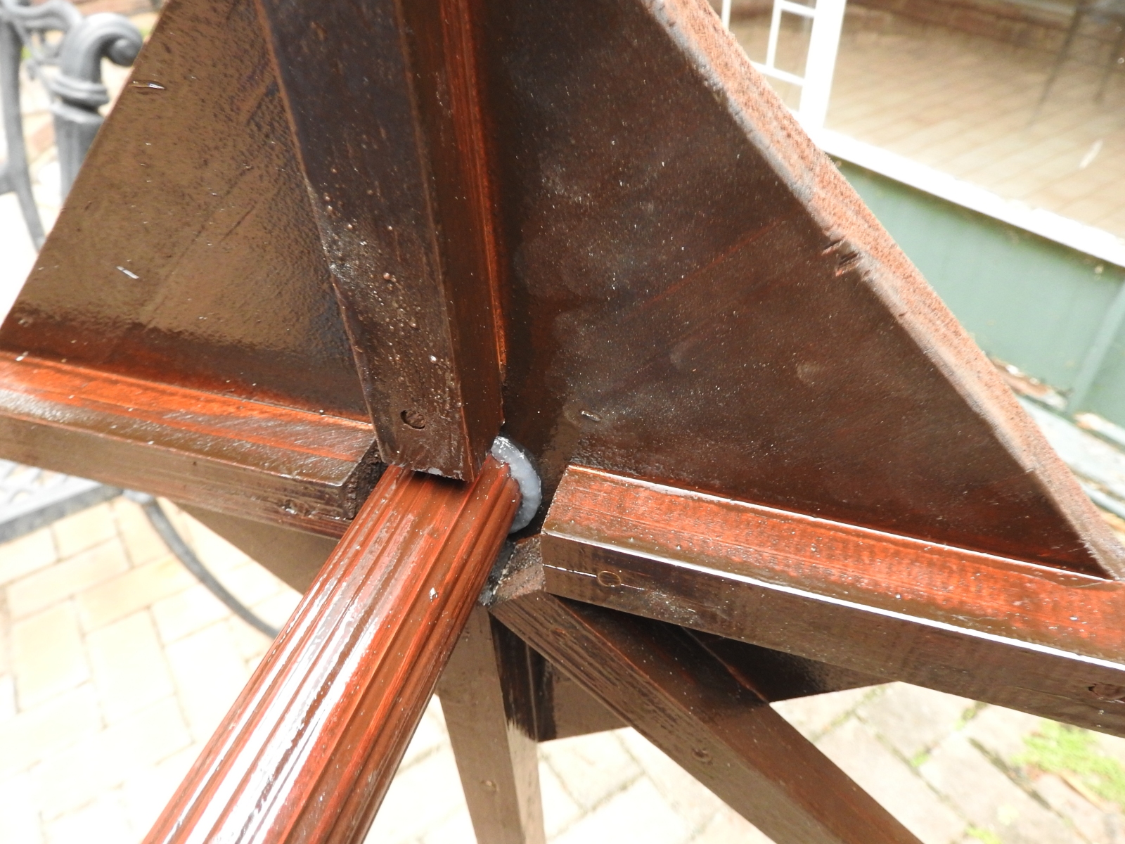
11 m Band Cobwebb antenna: Corner-end block
(click on the image for a larger version)
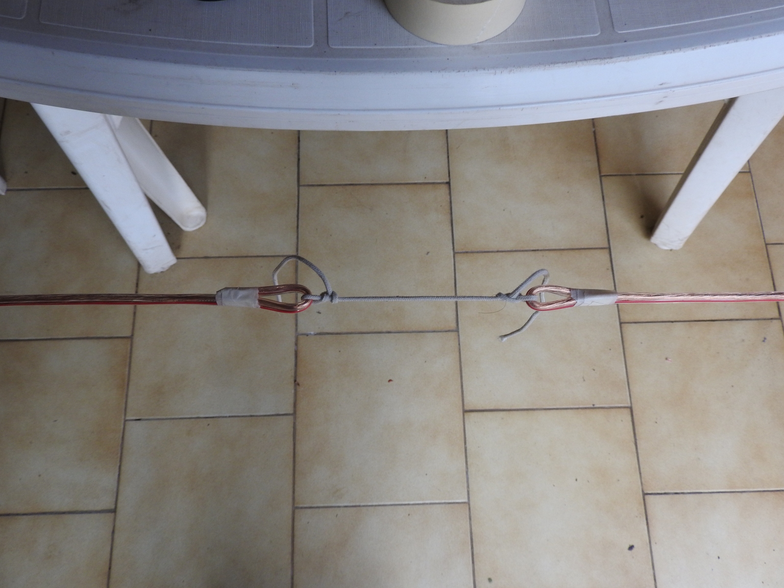
11 m Band Cobwebb antenna: Open ends tied with Dacron line
(click on the image for a larger version)
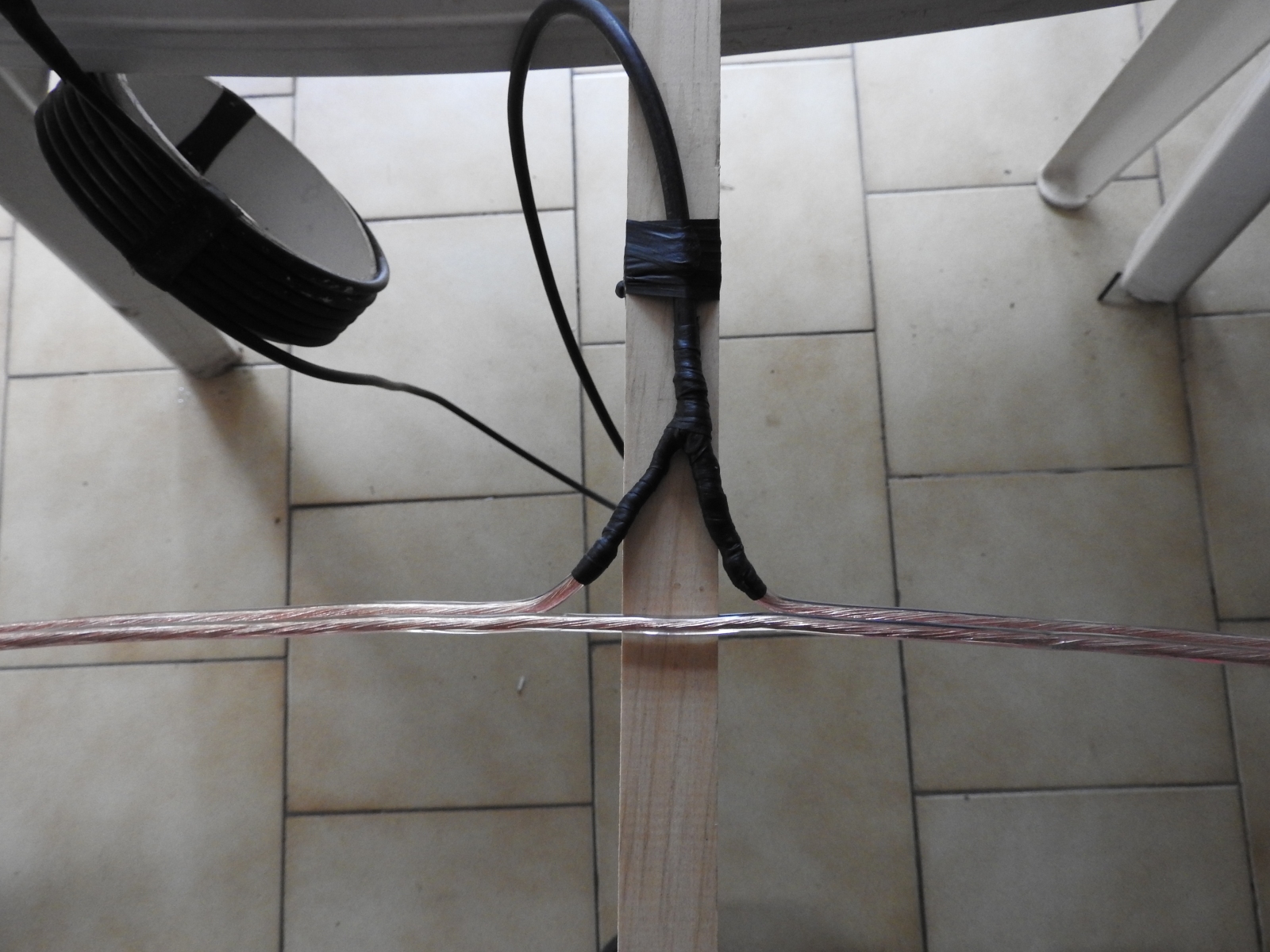
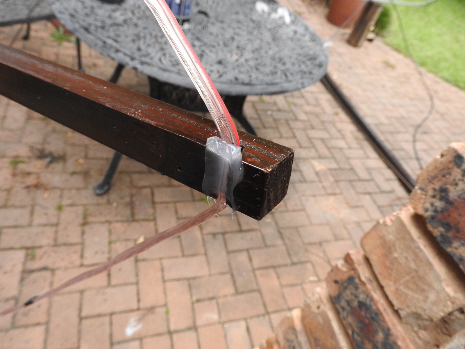
11 m Band Cobwebb antenna: Coax connection (self-amalgamating tape)
(click on the image for a larger version)
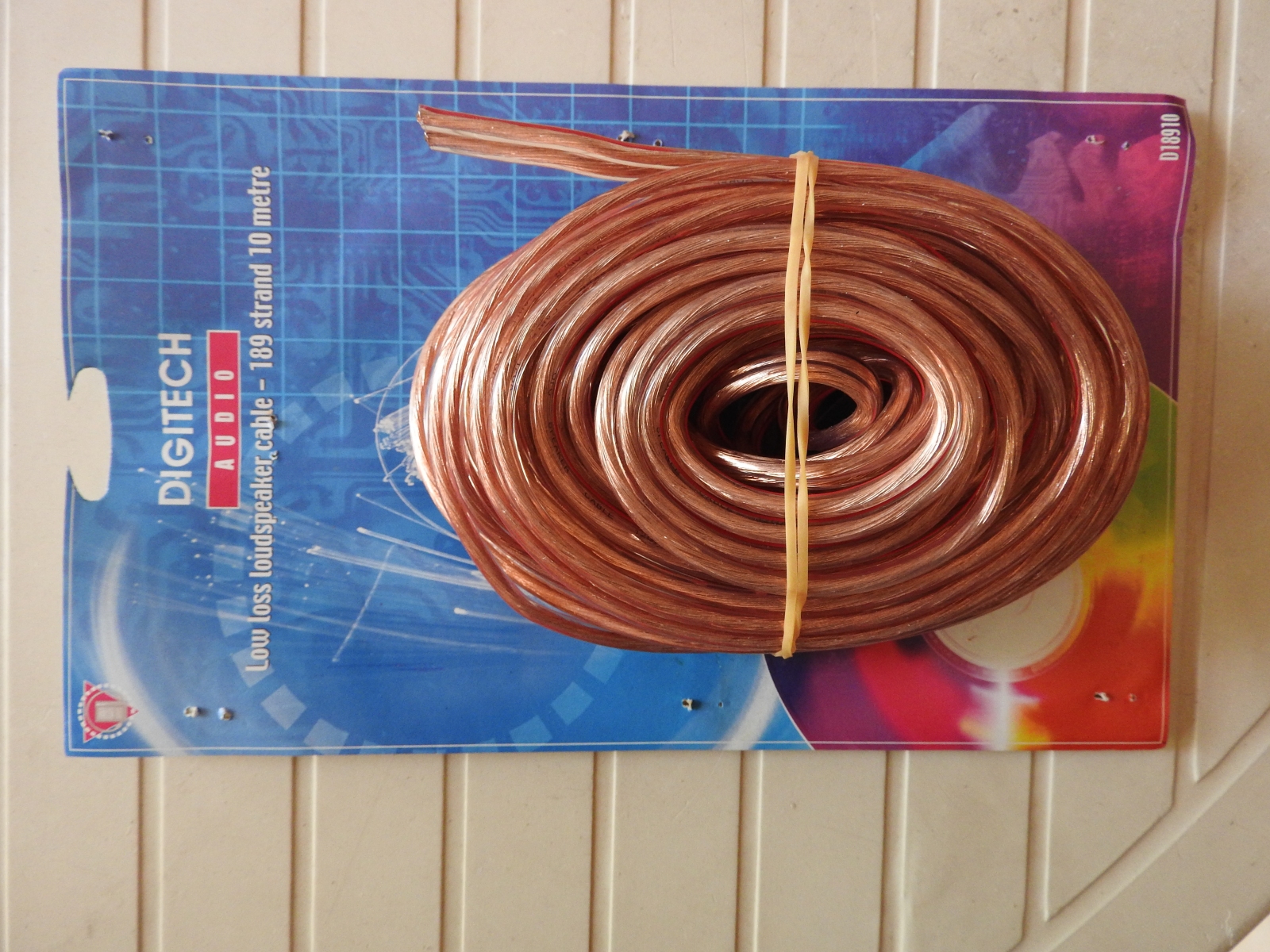
11 m Band Cobwebb antenna: Speaker cable
(click on the image for a larger version)
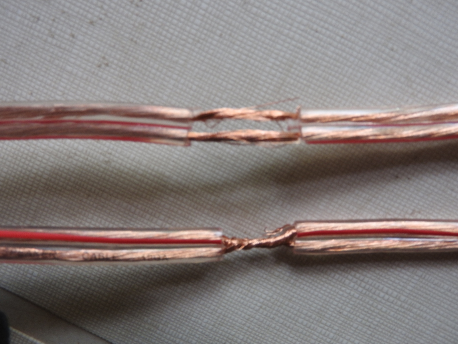
11 m Band Cobwebb antenna: Gamma match cable shorts (both wires of each cable to be shorted)
(click on the image for a larger version)
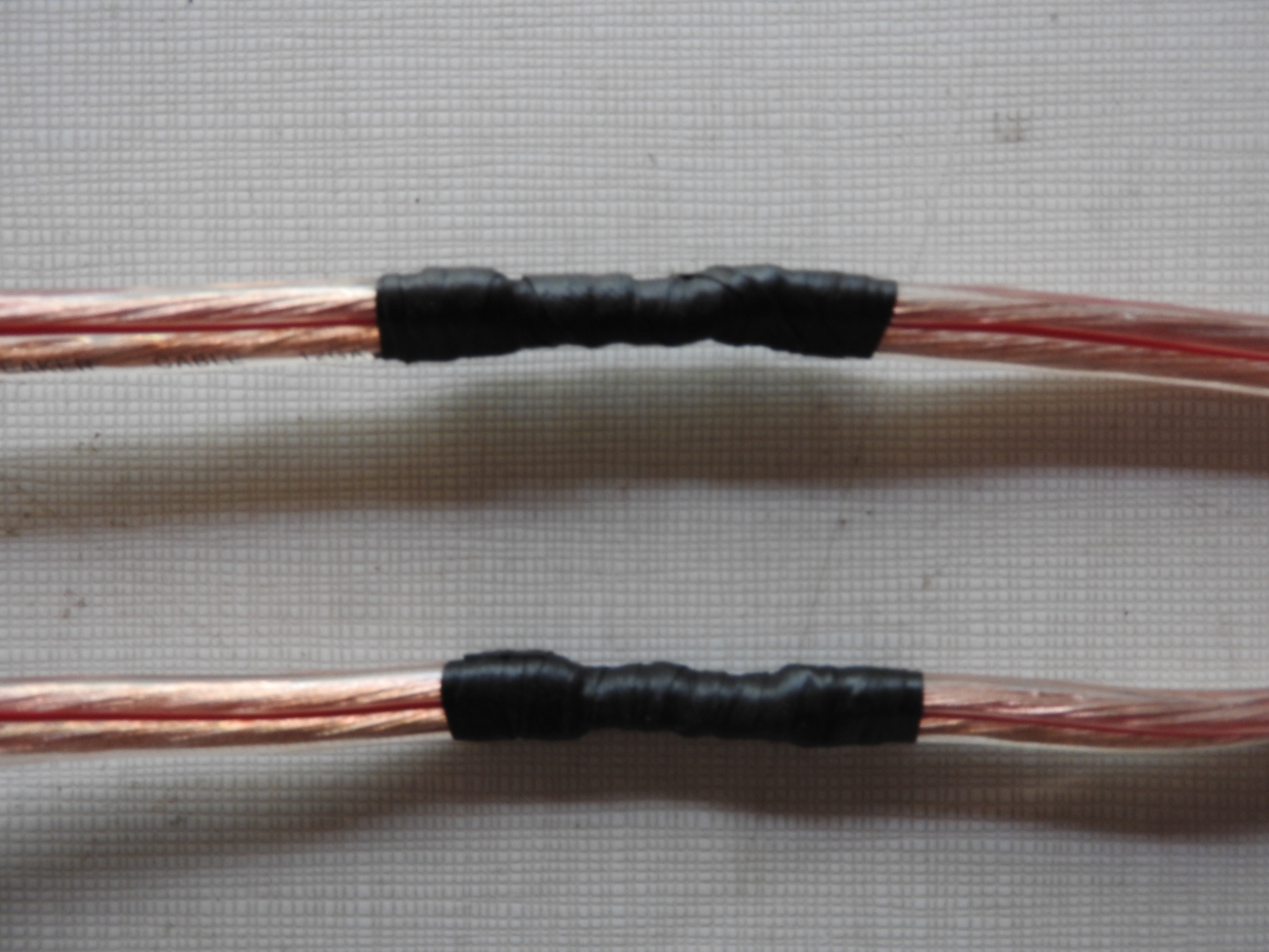
11 m Band Cobwebb antenna: Gamma match cable shorts sealed with self-amalgamating tape
(click on the image for a larger version)
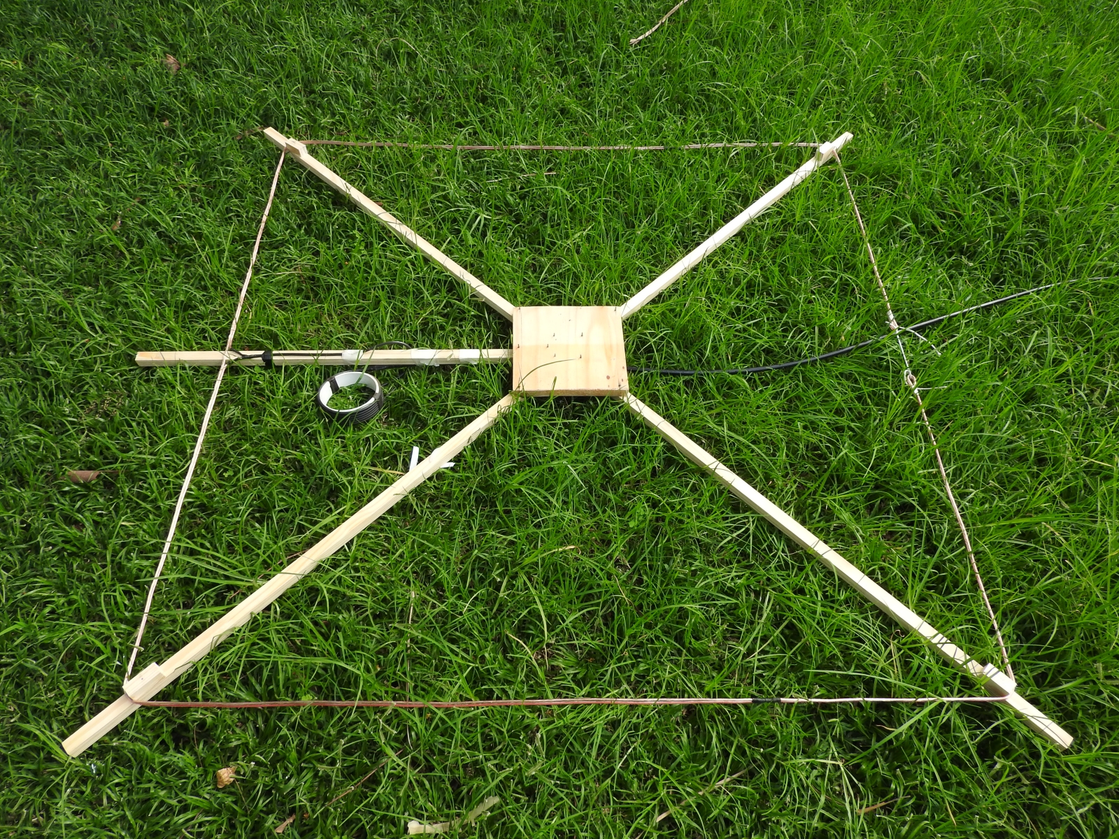
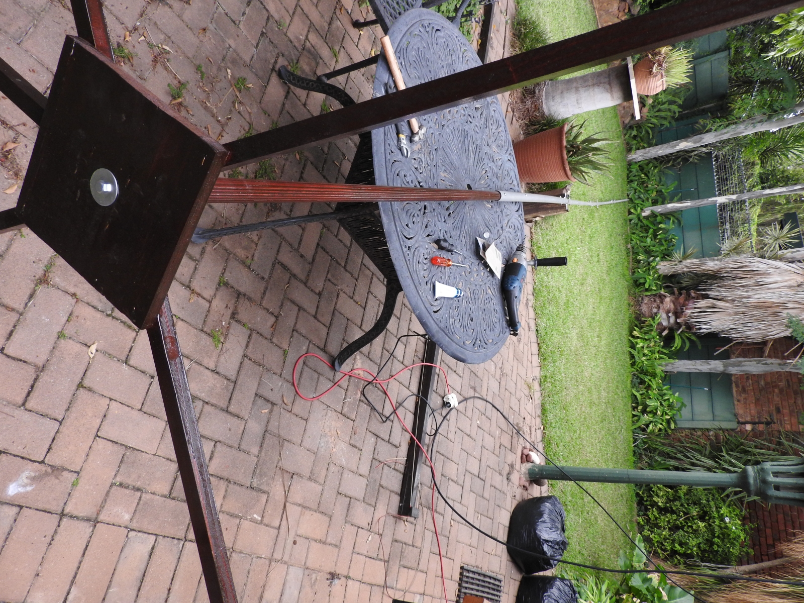
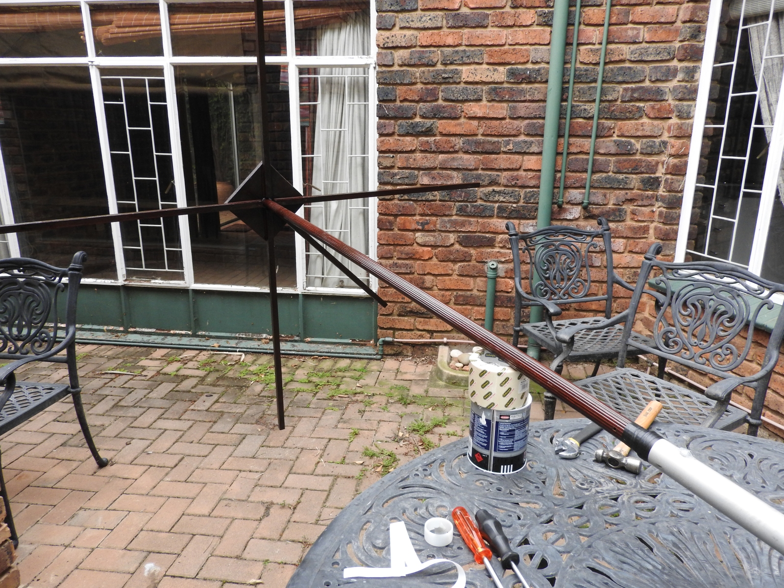
11 m Band Cobwebb antenna: Ready to test
(click on the image for a larger version)
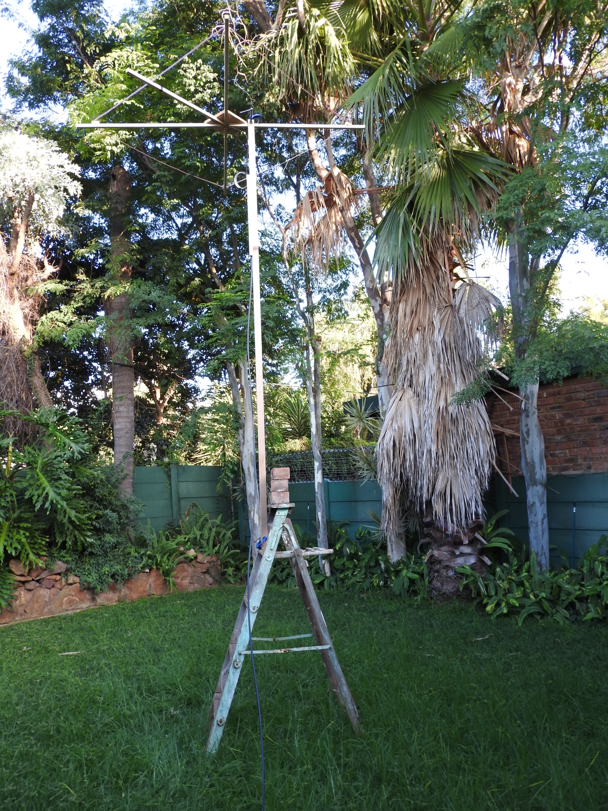
11 m Band Cobwebb antenna: Testing underway (mounted to ladder using clamps)
(click on the image for a larger version)
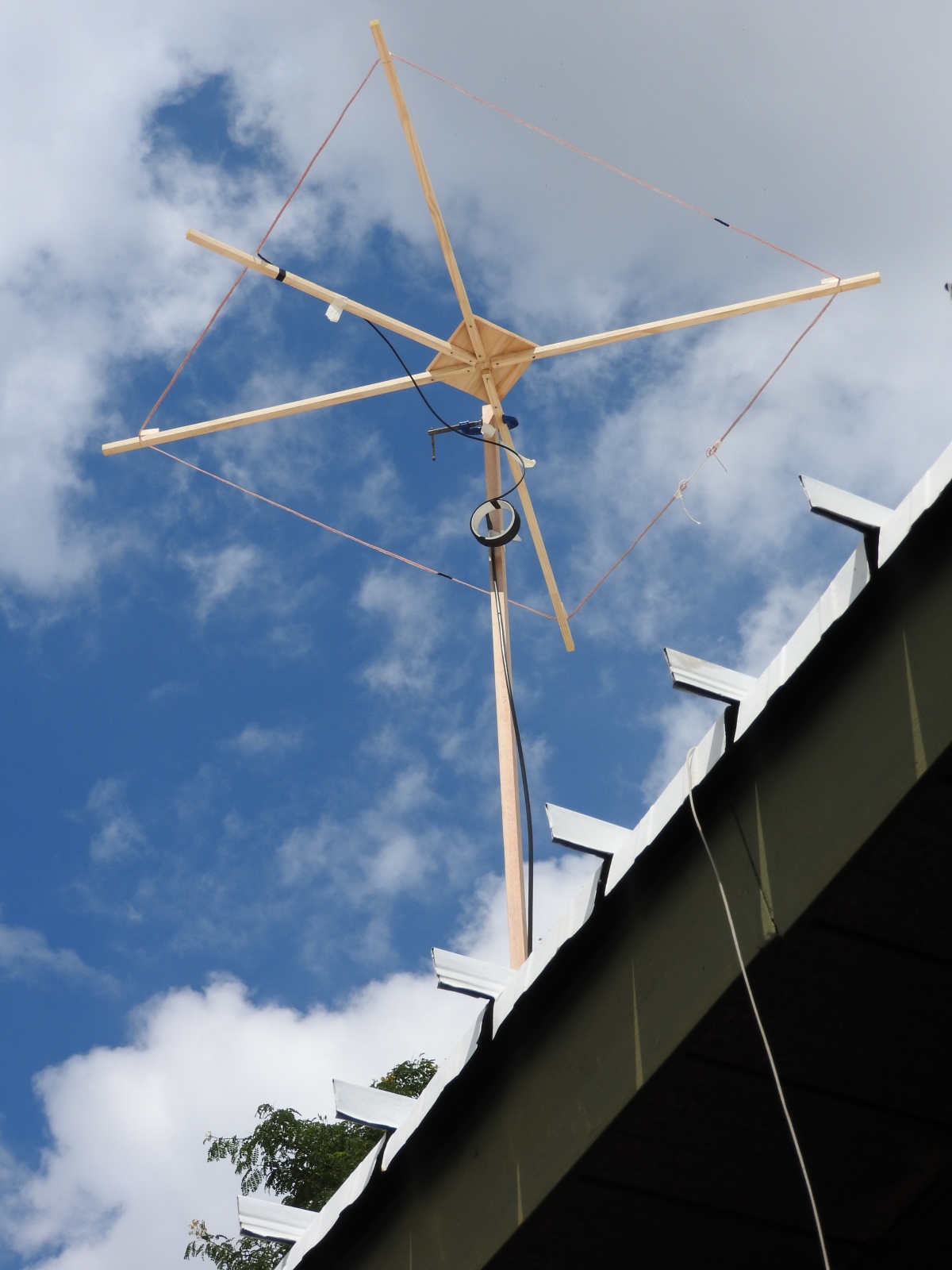
11 m Band Cobwebb antenna: Testing underway (mounted on roof)
(click on the image for a larger version)
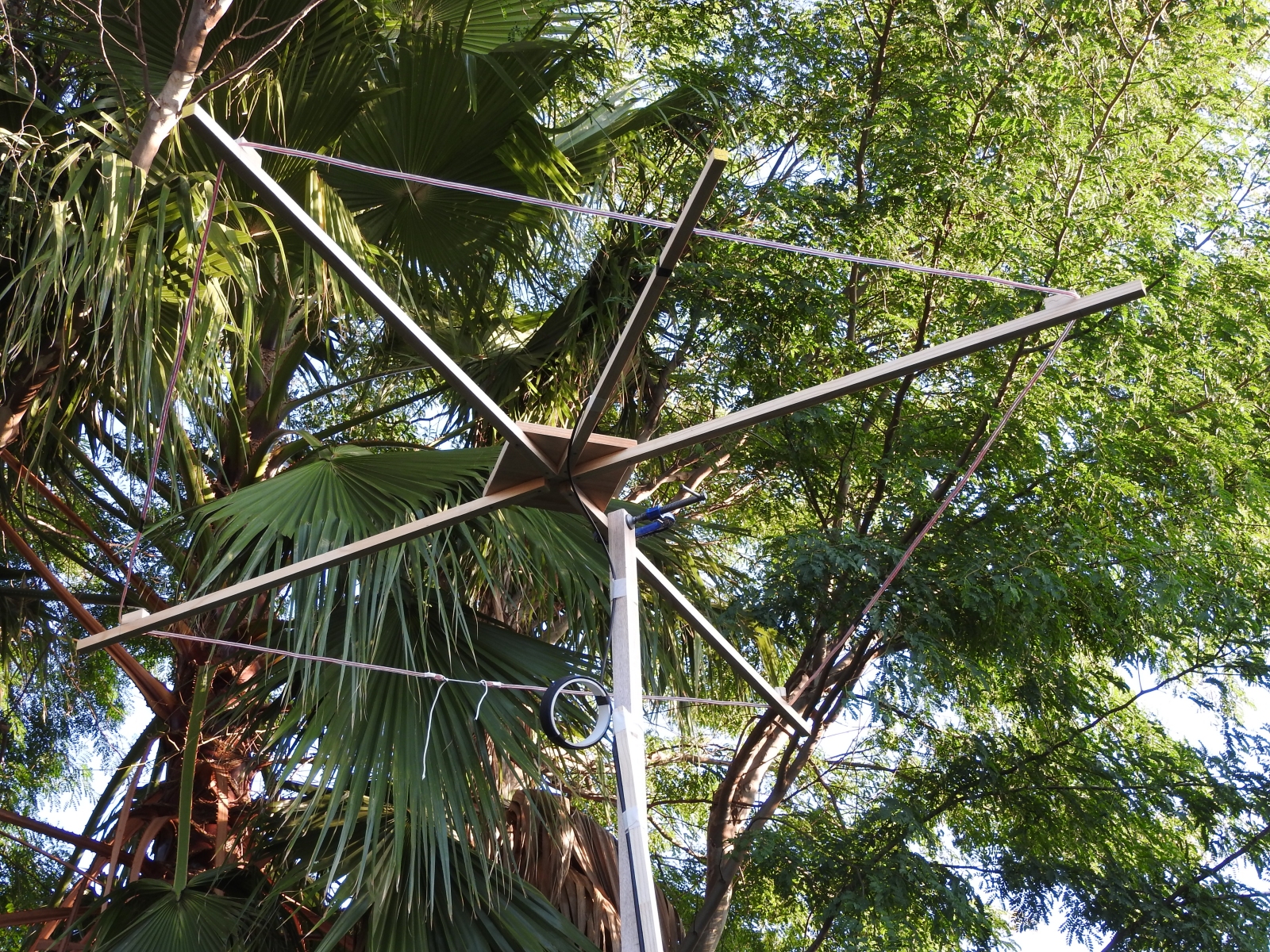
11 m Band Cobwebb antenna: Testing underway close-up
(click on the image for a larger version)
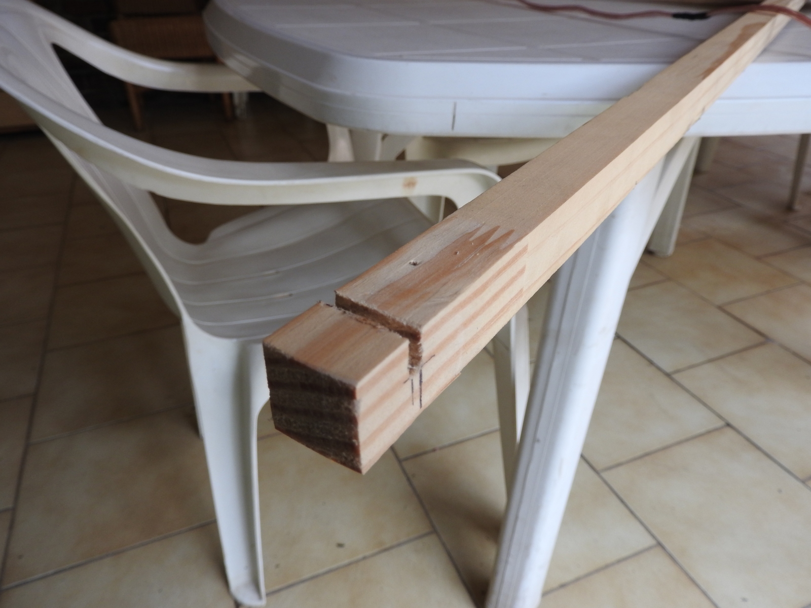
11 m Band Cobwebb antenna: Speaker cable slot at end of each spreader
(click on the image for a larger version)
11 m Band Cobwebb antenna: Painted with polyurethane wood sealer
(click on the image for a larger version)
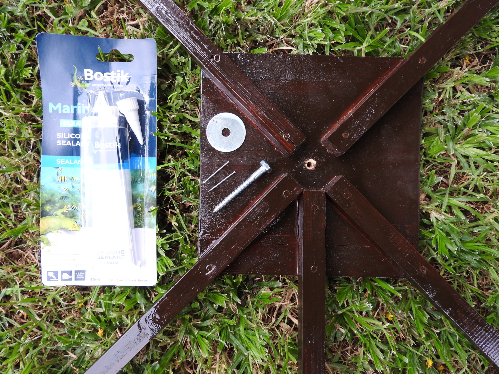
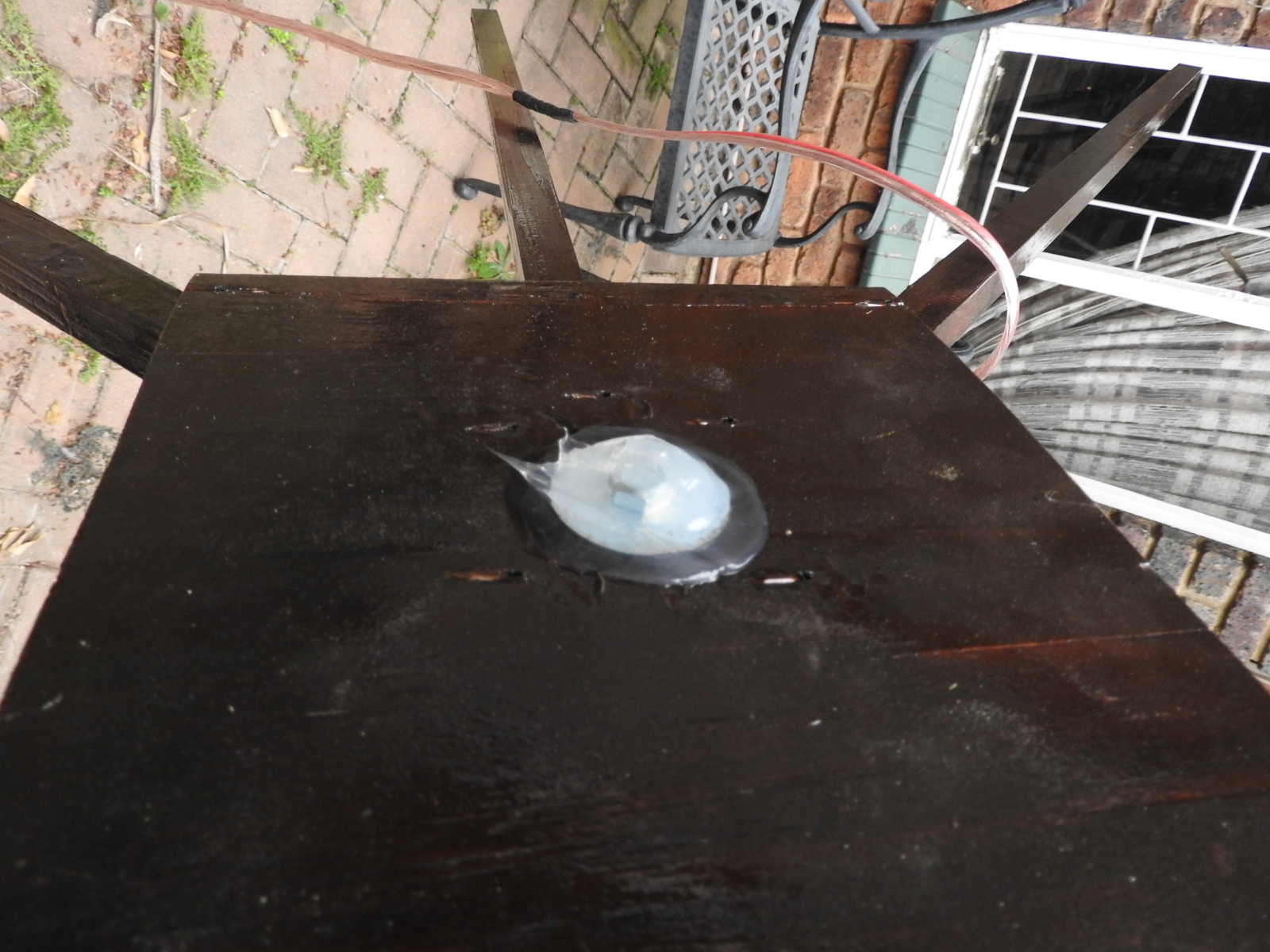
11 m Band Cobwebb antenna: Mounting screw, large washer, nails and Marine silicone sealer
(click on the image for a larger version)
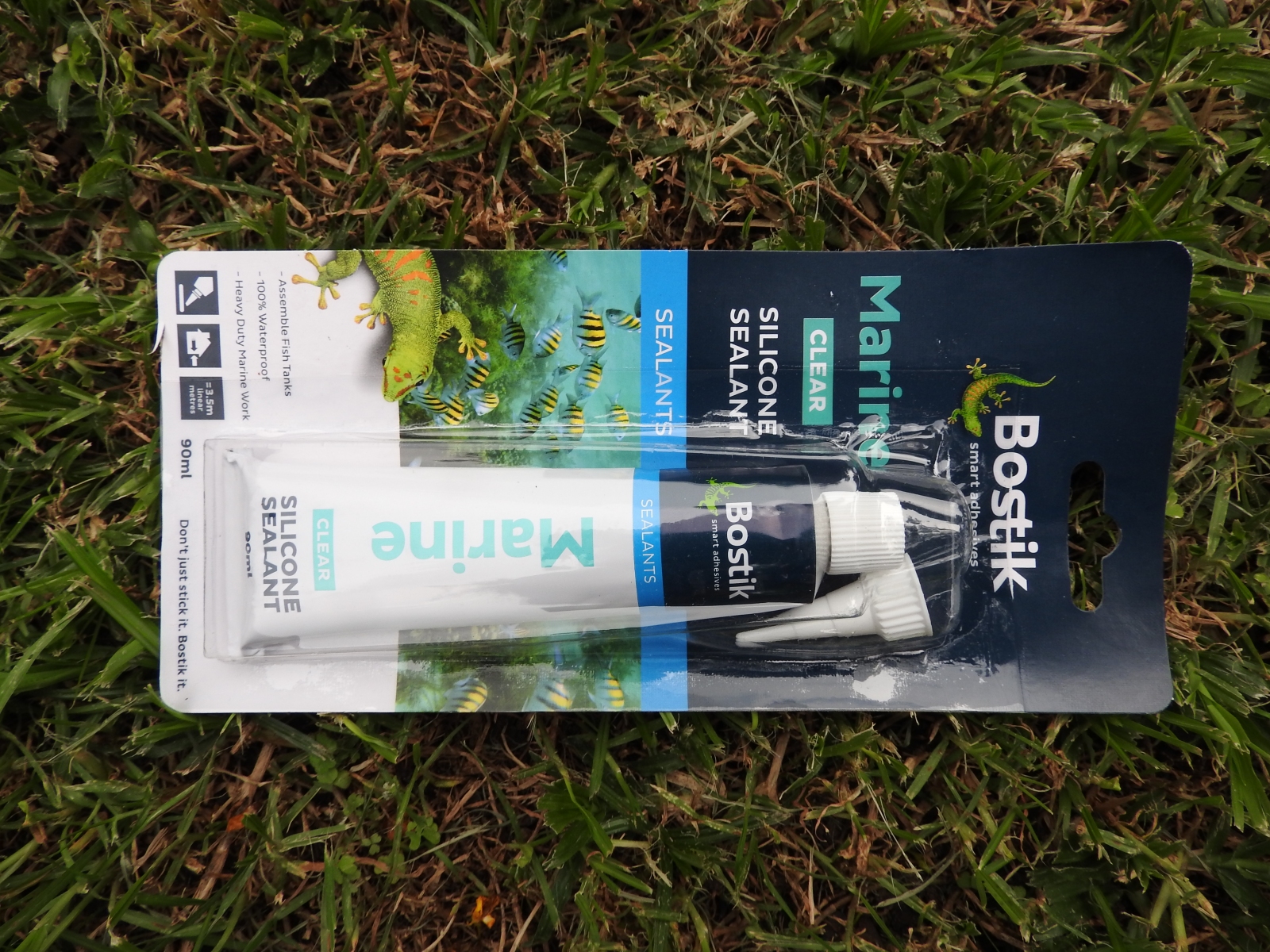
11 m Band Cobwebb antenna: Marine silicone sealer
(click on the image for a larger version)
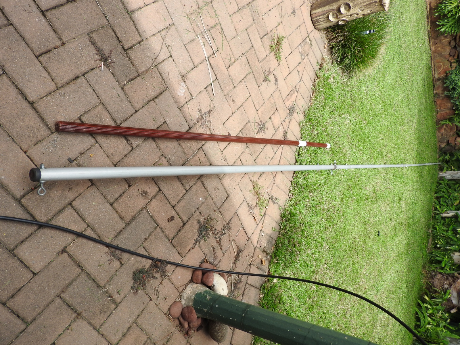
11 m Band Cobwebb antenna: Main and intermediate mast
(click on the image for a larger version)
11 m Band Cobwebb antenna: Steel wire hooks
(click on the image for a larger version)
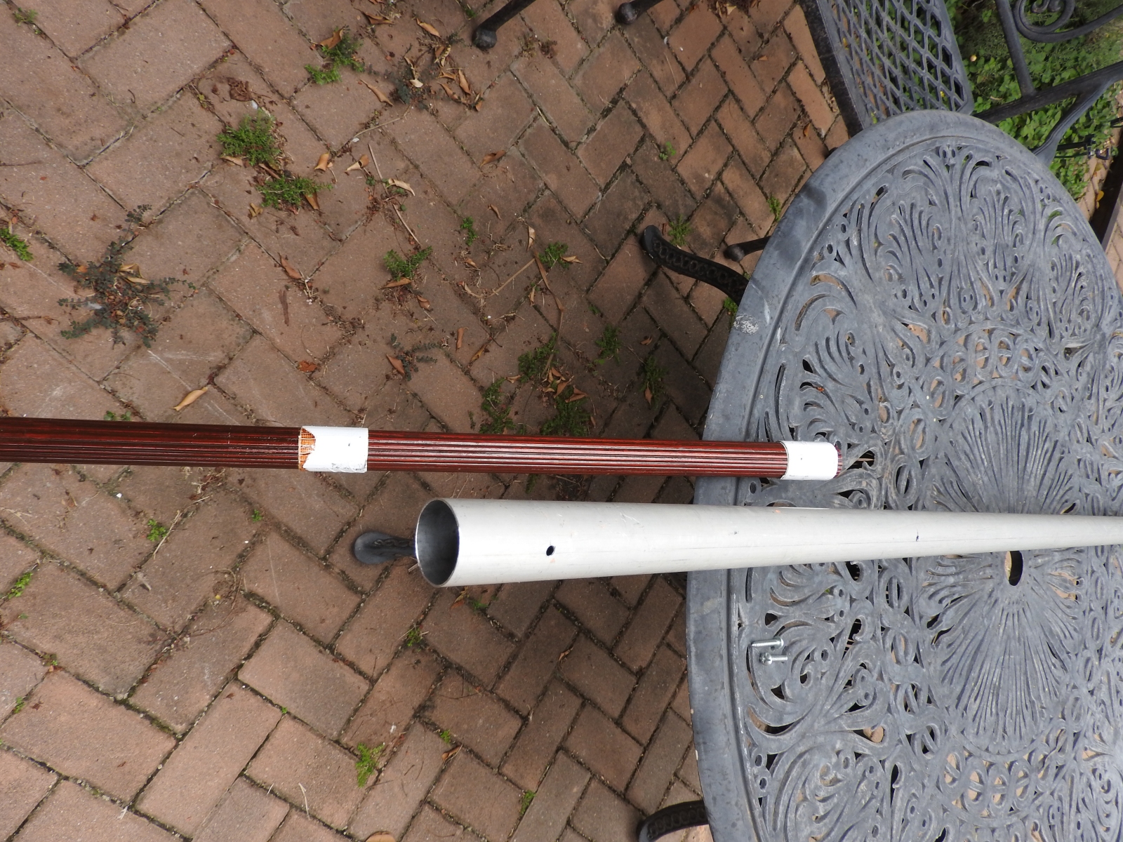
11 m Band Cobwebb antenna: Intermediate mast wrapped in duct tape to fit tightly inside main mast
(click on the image for a larger version)
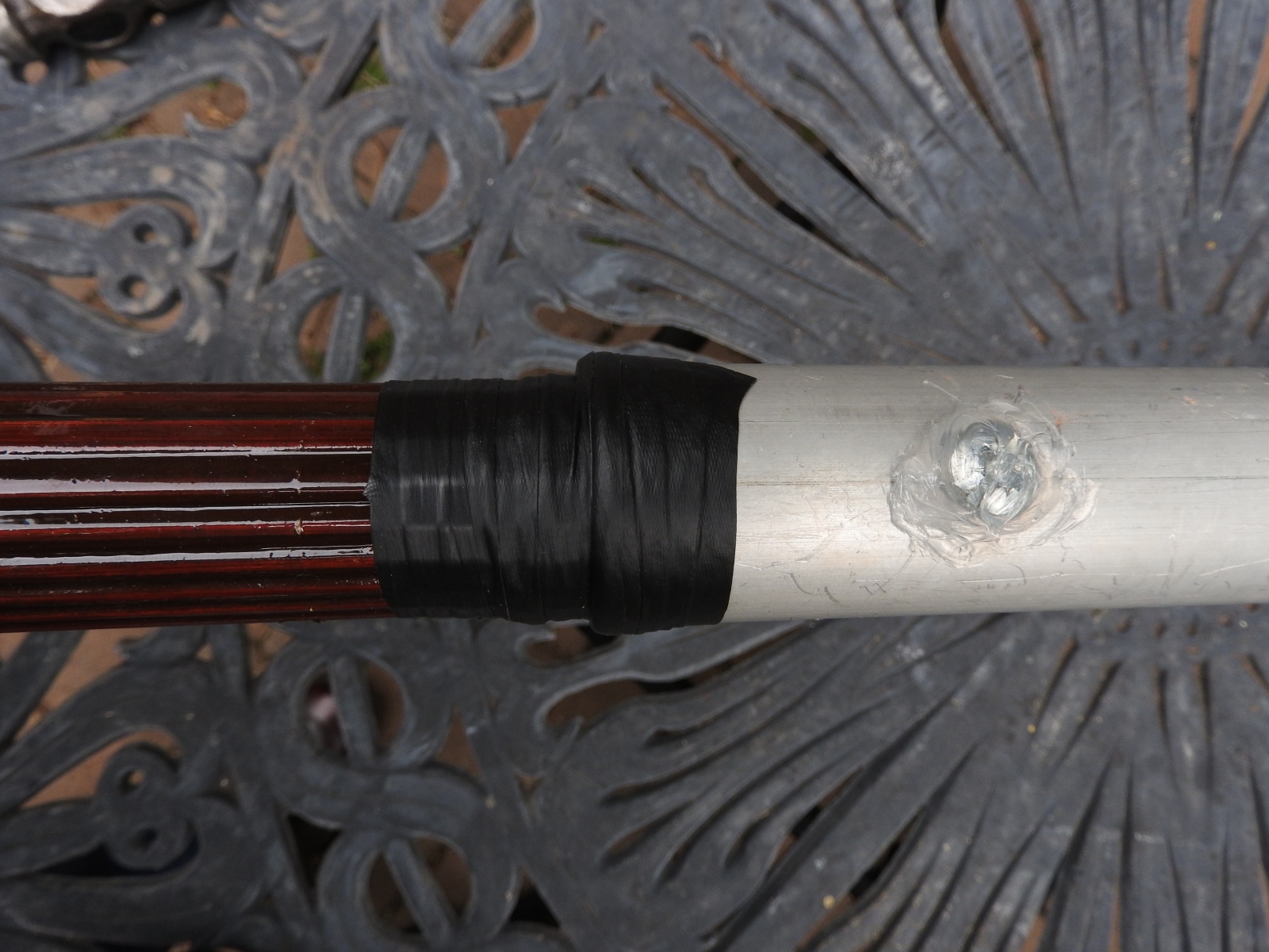
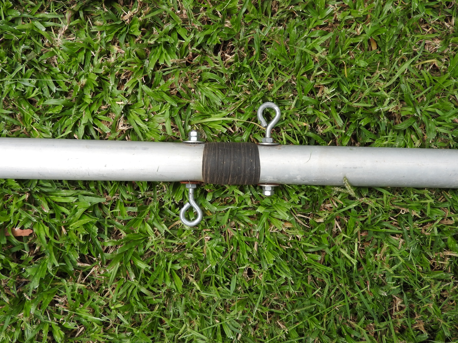
11 m Band Cobwebb antenna: Masts joined, screws sealed with Marine silicone sealer and mast with self-amalgamating tape
(click on the image for a larger version)
11 m Band Cobwebb antenna: Mounted to intermediate mast using screw and two nails either side of screw
(click on the image for a larger version)
11 m Band Cobwebb antenna: Mounting screw and two nails sealed with Marine silicone sealer
(click on the image for a larger version)
11 m Band Cobwebb antenna: Intermediate mast and antenna join sealed with Marine silicone sealer
(click on the image for a larger version)
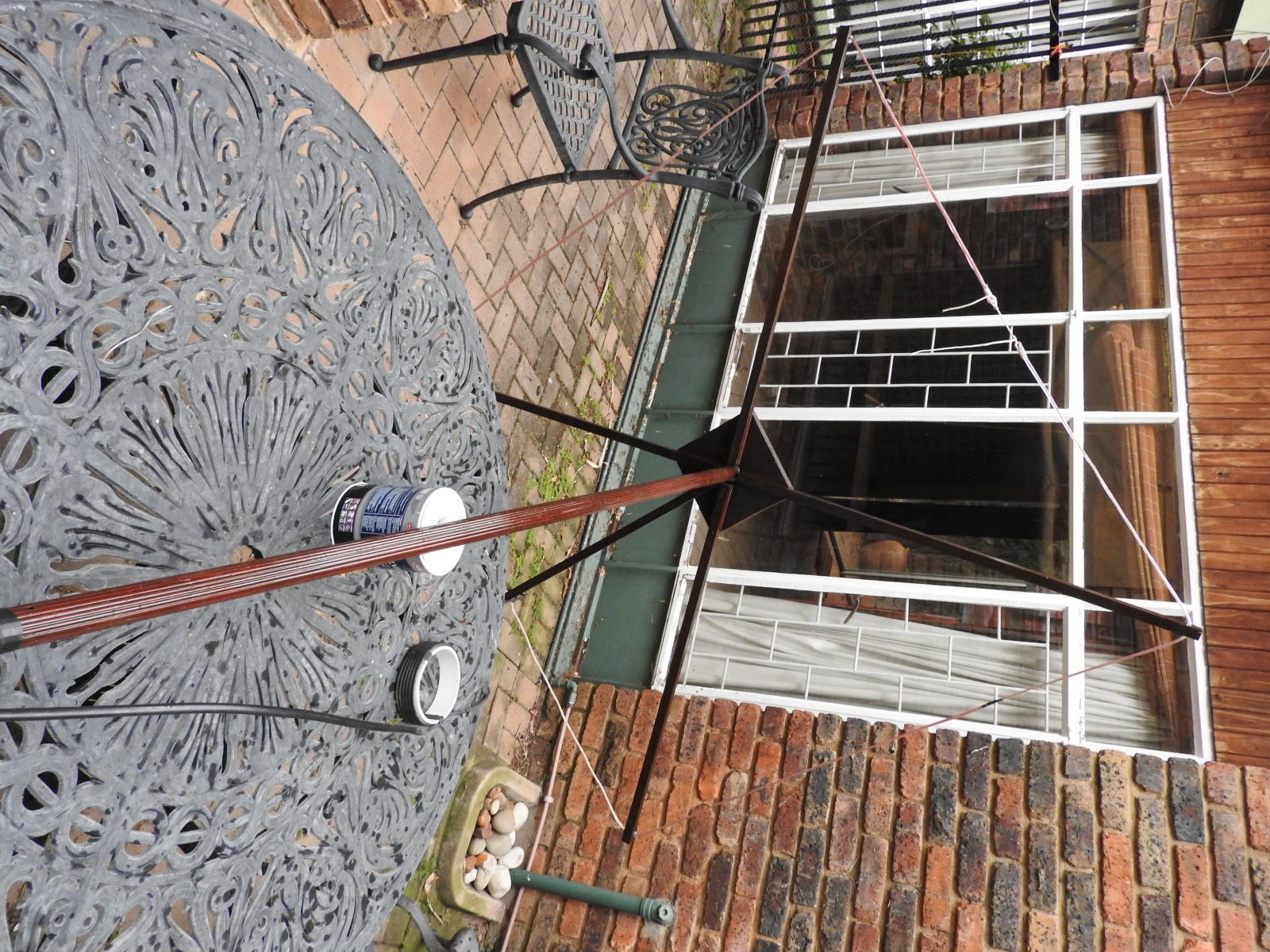
11 m Band Cobwebb antenna: Ready for speaker cable, balun and coax installation
(click on the image for a larger version)
11 m Band Cobwebb antenna: Speaker cable mounted
(click on the image for a larger version)
11 m Band Cobwebb antenna: Speaker cable kept in place using Marine silicone sealer on each spreader
(click on the image for a larger version)
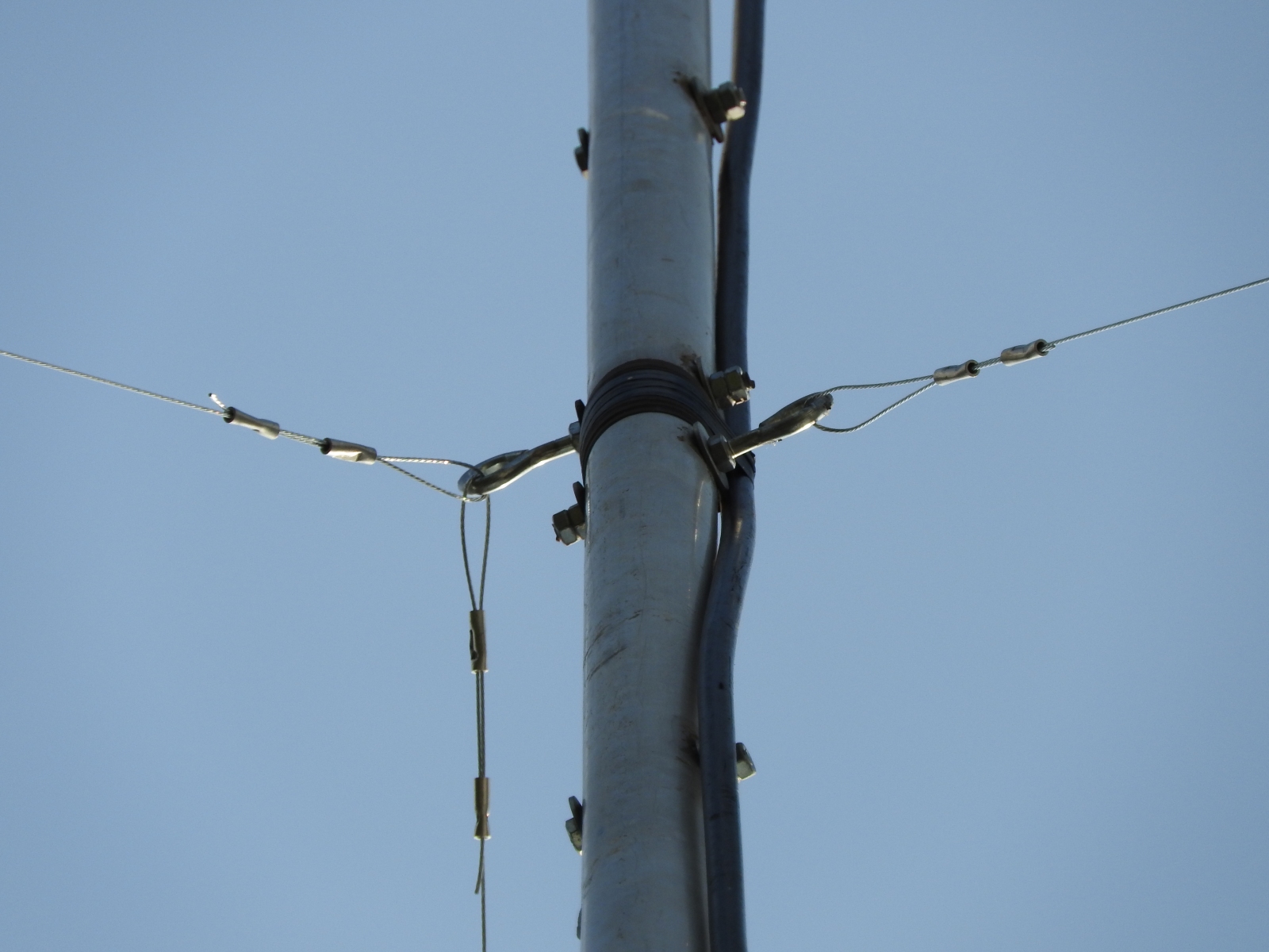
11 m Band Cobwebb antenna: Steel wire guys
(click on the image for a larger version)
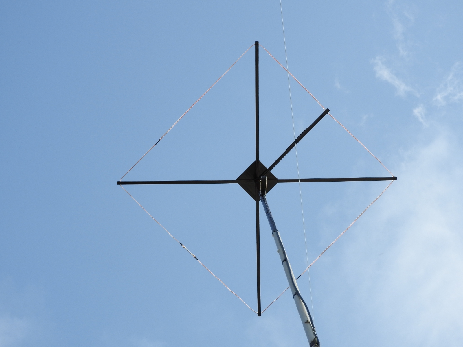
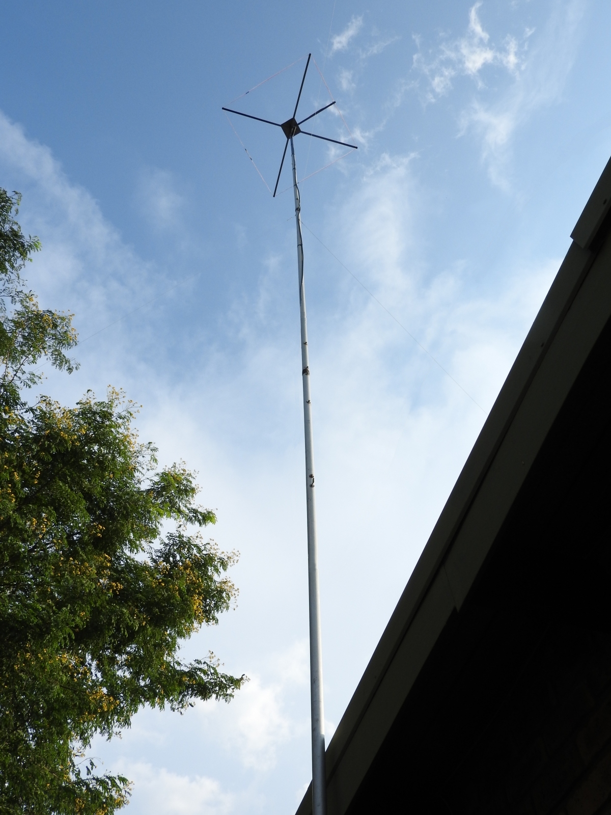
11 m Band Cobwebb antenna: Final installation completed
(click on the image for a larger version)
| Type | Cobwebb (Gamma matched dipole loop) |
| Frequency | 11 meter Band (centred at 27.500 MHz) |
| Directivity | Omni-directional (horizontally polarized) |
| Height above ground | 11 m (ideal height) |
| Gain | 6.56 dBi (at 11 m above ground) |
| Take-off/elevation angle | Approximately 14 degrees (at 11 m above ground) |
| Band width | 220 kHz (measured at the 1:1.5 VSWR points) |
| Antenna cable | Speaker cable (189 copper strands with polyethylene insulation approximately 1 mm thick) |
| Speaker cable length | 5.250 m (cut cable a few cm longer than required to allow for length adjustment) |
| Current Balun | 7 turns of RG-58U coax close wound side-by-side with a 12 cm diameter air core |
| VSWR | Less than 1:1.3 at 27.560 MHz and 1:1.5 at 27.420 MHz and 27.640 MHz respectively |
Antenna's
 Contents and images
© 1998 to 2024 RaptorZone v8.0
All rights reserved